Function
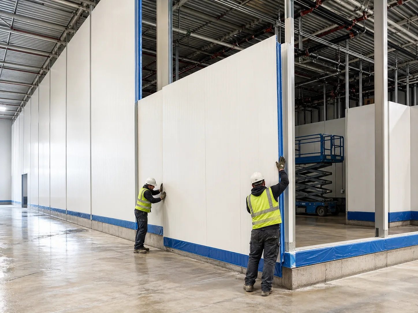
Block vapor migration into the insulation.
Water vapor diffuses from warm side to cold side continuously through any permeable material. In cold storage, the warm-to-cold vapor pressure differential runs 24/7 for the life of the building. Vapor that reaches the cold face condenses, often freezes, and destroys the envelope from the inside out.
- Block vapor migration into insulation
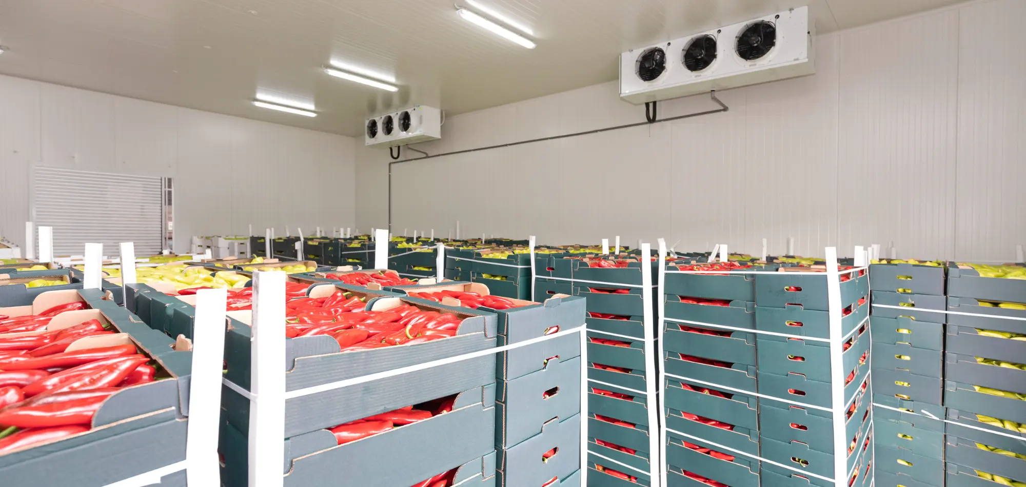
- Prevent condensation inside the envelope assembly
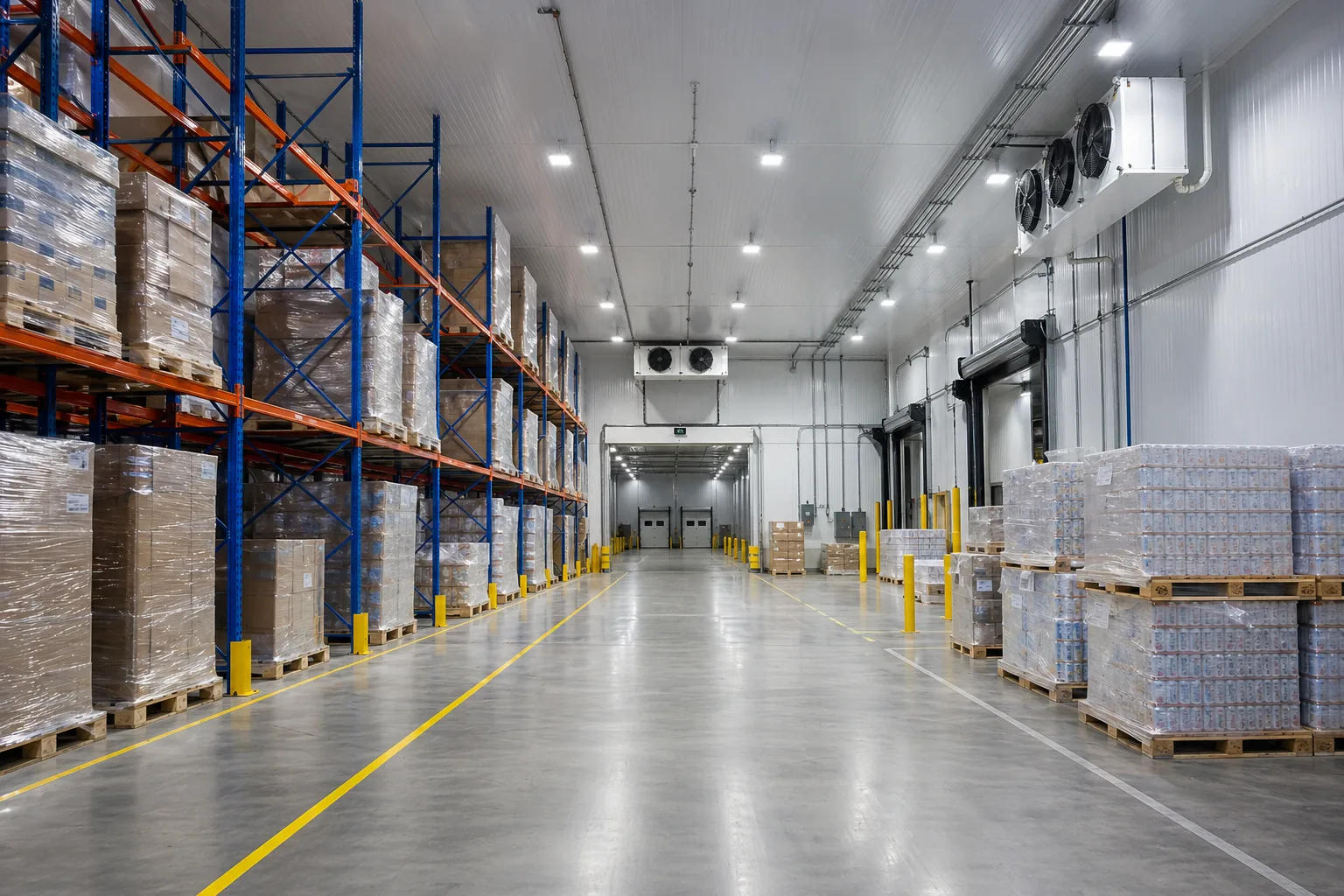
- Maintain insulation R-value over time
- Prevent structural corrosion at panel facings